Remote Shooter BT 3.0, is a hardware and software solution for the remote control of the digital cameras click away BT with Time Lapse functions and events, continues to evolve we have now developed new GUI controls, creating Applications for Android devices using App Inventor for giving anyone the ability to create other functions, and from PC using Microsoft VC2005 or SharpDeveloper. For experienced programmers who had special needs we will make available the source code for developing with Google Android Eclipse toolkit.
The project started about 2 years ago, thanks to the support of this blog, was initially thought to control some digital cameras like the Nikon D50, but can control many other digital cameras that use PTP standard (attention will be focused particularly on DSLR from Nikon and Canon, and on their respective compact Coolpix or Powershot), it all depends on the specific functions provided by the camera you own.
Once connected the device to the USB port on the camera, it will automatically call the discovery of available features; Since that time with Remote Shooter 3.0 you will be able to control the main functions of the camera. A stereo jack 2.5 port is available (Focus & Release) to give the possibility of remote control (shutter and Time Lapse) even in cameras that are manageable via PTP. In this case you will need to obtain an adapter cable (on ebay, for example) with the right connector for your camera.
Main functions:
- Remote Shoot;
- Time Lapse (interval in seconds, number of repetitions);
- Shutter Speed Settings; (if your camera exposes its PTP commands);
- Aperture Settings; (if your camera exposes its PTP commands);
- Iso Settings; (if your camera exposes its PTP commands);
- Bracketing on/off; (if your camera exposes its PTP commands);
- Shake & Shoot (the app reads the accelerometer data of android smartphones);
- Sound & Shoot (the app reads the values of the smartphone's microphone, the threshold required to trigger noise is adjustable);
- Read & Shoot (the app reads and executes a programmable sequence of actions)
- Your smartphone display of the thumbnail of the picture just taken, or even the last 10;
- USB Host mode to connect to the camera (the functions depend on the characteristics of the camera)
- 2.5 mm Jack port to fire-based functionality and click (available on many SLR cameras) in case the PTP USB mode is not possible.
- Port i/o expansion for external sensors/actuators (eg light sensor or flash)
- Wireless firmware Upgrade (based on Microchip's bootloader)
- Li-Po Battery 750mAh, rechargeable from any micro-usb charger
For communication with the interface unit is connected to the camera, we have created an app for Android smartphone/tablet and provide also a Windows application, giving way to the more you its smart interface if not satisfied that we have created. However thanks to this choice to leave open source code, you will be able to add new features such as click upon receiving a message (SMS), the position detected by GPS etc.
Communication between PC and Smartphone/our device Remote Shooter relies on the Protocol mode Bluetooth SPP (Serial Port Profile). It occurs with the exchange of messages that provides a set of read/write commands specifically implemented and that define all the effects a simple but effective scripting language, by means of which you can give simple instructions in sequence, even on a text file that will be read from the smartphone app, and sent one by one to the device connected to the camera.
ALSO READ: Samsung Galaxy S4 Zoom Specs
The Basic setting commands:
ENSENS = 0 or 1:::::::::::::::: enables/disables the timer sensor
ENSENS? :::::::::::::::: to get status
DELAYSENS = microseconds:::::::::::::::: microseconds to enable
DELAYSENS? :::::::::::::::: to obtain the value set
ENTIMER = 0 or 1:::::::::::::::: enables/disables the timer
ENTIMER? :::::::::::::::: to obtain the value set
TIMEINT = seconds:::::::::::::::: set timer seconds
TIMEINT? :::::::::::::::: to obtain the value set
TIMERIP = number of repetitions:::::::::::::::: set timer repeats
TIMERIP? :::::::::::::::: to obtain the value set
The PTP communication commands with the camera:
SHOOT:::::::::::::::: Shutter Control with focus
GETPROP? ::::::::::::::::: to get the properties that are exposed by the camera
GETEVENT METHOD? ::::::::::::::::: to get events exposed by the camera
GETOPCODE? ::::::::::::::::: to obtain the Opcode (snap-type commands etc) exposed by the camera
SENDCMD! .0 .0 .0 .0 100E .0 .0. where the first parameter is the command (in this example the PTP standard shutter)
GETPROPVAL? or returns the value or code with the error
SETPROPVAL = returns the result with the code.
GETOBJHDL? Command to get all handles of all the images present on the machine
GETOBJINF? handledapassare ... command to get the info of the image, is always called before taking the image with subsequent calls. Example called GETOBJINF? 00000001.
GETTHUMB? handledapassare ... ... Command to get the thumbnail of the image request, GET command Example.
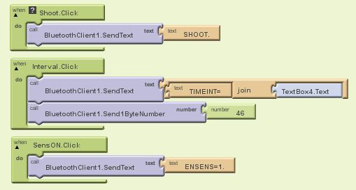
Over time, and also for any suggestions, will be made available additional commands on the firmware, upgradeable via bluetooth. In order to offer maximum flexibility of use, trying to cover the needs of both beginners and professionals, we took two paths to implement on Android the management interface and control. The first is using App Inventor, Google Chart Tools extremely intuitive although not allows complete control over resources of a smartphone, with an App that will provide the basic functions (similar to version 2.0) where even beginners can still start to customize its interface. Here an example of commands sent over Bluetooth when you click on their respective buttons: SHOOT, interval (Time Lapse) and Enable the sensor.
The second, much more complete, and opened a thousand applications is via the SDK integrated development tool (ADT Android Developer Tools). The tool is really powerful, there is virtually no limit to the realization of any application.
We thought even for a third option, a cross between the two tool, that permits to those who are completely fasting of technology and development, to use a simple but effective "scripting" language, a batch, put on a text file using a button of the JPA will be read and executed. The idea we came up with imagining a possible application of the laboratory, where it is necessary to have a certain automatism that repeat a series of base operations several times.
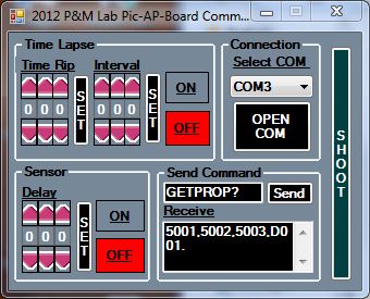
For the PC version, we will provide the sources of the GUI shown in figure, developed with Microsoft VC2005.
It should be noted that in the PC version is a useful debugging feature to display all commands, properties, and events that the camera has. This feature can be used to create an online database of cameras, to support all those who need to develop their own applications based on specific cameras.
But back to the most interesting for the most experienced and curious, on the development with Eclipse: Google Sdk for Android. The draft communication between smartphones and the physical drive connected via USB to the camera, is the party structure of the sample provided bluetooth chat right from google Android sdk, hence were immediately implemented some more sophisticated functions, such as the transport of the thumbnail from the machine to the phone and its view, or click sound triggered by an event detected by the phone's microphone. For those who want to try, first of all you must keep in mind a more specific designation on the APA, sources on the use of bluetooth in android serial: va in fact set a specific UUID, without which no serial communication (SPP) with no device:
//Unique UUID for this application
//for Bluetooth serial board
private static final MY_UUID UUID = UUID. fromString ("00001101-0000-1000-8000-00805F9B34FB");
Let us now more specifically one of the functions present on the APP, the trigger that triggers the shutter command when the smartphone's microphone detects a sound/noise that exceeds a certain preset threshold. The trigger command was implemented by using a separate thread to avoid blocking the whole app. Programmers should note that on Android, and on all phones generally, one of the things that are important for the proper management of the App is to not tie the actions/functions directly to click/touch, but separate from the action events related to them. The sound trigger was implemented through android.media.MediaRecorder class that allows you to record only audio but not video, specifically for the shot tied to a sound event is used the method getMaxAmplitude () which returns the absolute maximum size that has been sampled since the last call to this method. The return value is an integer, then if the entire returned is greater than the value set as our variable threshold (sensitivity), the App will send the command to SHOOT towards the physical drive and consequently towards the camera. The thread, once launched, will continue reading the value ready to shoot.
Here's the code of our function:
private class GetMaxAmplitudeXS extends Thread {
public GetMaxAmplitudeXS () {
}
public void run() {
Sound: int = 0;
while (true)
{
Sound = 0;
try {thread.sleep (10);
} catch (InterruptedException e) {
and printStackTrace () method;
}
try {
Sound = recorder. getMaxAmplitude ();
} catch (IllegalStateException e)
{
Log (TAGS, ". getMaxAmplitude", e);
}
mProgressAudio; setProgress (Sound);
if (Sound Sensitivity >)
{
The Log (TAG, "SHOOT.");
if (rShootService. getState ()! = RemoteShootService. STATE_CONNECTED) {
Message msg = mHandler. obtainMessage (RemoteShoot. MESSAGE_TOAST);
Bundle bundle = new Bundle ();
bundle. putString (RemoteShoot. TOAST, "You are not connected to a device");
msg. setData (bundle);
mHandler; sendMessage (msg);
} else {
String Msg = "SHOOT.";
byte [] send = Msg. getBytes ();
rShootService. write (send);
}
Hardware
PIC24FJ64GB002 16 bit processor, USB-OTG 8 k Ram, 16Mips @ 32Mhz
Program Memory 64 k Flash
Bluetooth serial communication module HC-05 class2 certified 30 ft/10 Mt coverage
Power supply LiPo 3 .7V 750mAh battery onboard
The circuit diagram, PCB layout, is still in the process of optimization, and will be offered in Open Source if we are going to complete the project. The whole thing was created with Eagle 6.0 version; for the 3D representation we are using the excellent plugin that creates a file eagleup 3d compatible 3D cad, Sketchup. To give you an idea we list the most significant part of the wiring diagram.
The core of the device is the microchip PIC24FJ64GB002, the choice fell on this microprocessor for its small size, low power consumption thanks to the NW of Microchip, the internal clock that needs no oscillation circuit (quartz and capacitors). For communication between PC and smartphone/physical unit we chose the serial Bluetooth module HC-05, this component has a low power consumption (approx. 8 mA) after pairing and discovery (on average about 25mA). For the power supply of the device we opted for a lithium polymer battery from 750mA. The characteristics of these batteries should ensure sufficient autonomy. For specific charging circuit for Li-Po was chosen the MCP73831 chip, also from Microchip.
Allow me a few words on the future of the project: considering the rapid development also in Italy the phenomenon of Crowdfunding, we thought we'd get in the game, after a selection of the main world platforms, the choice fell on Indiegogo, first of all because it is perhaps the main competitor of KickStarter, with the advantage that gives you the ability to access to non-resident makers in USA.